Anodal capture
Tracing
Manufacturer Medtronic
Device CRT
Field Left ventricular pacing
N° 5
Patient
81-year-old man implanted with a triple chamber pacemaker Consulta CRT-P with bipolar RV and LV leads for severe ischemic cardiomyopathy with right bundle branch block; routine follow-up; the ECG shows two slightly different patterns of the paced QRS; LV pacing amplitude is set at 3.5 V/0.4 ms in a (distal) tip LV – ring (anode) RV.
Graph and trace
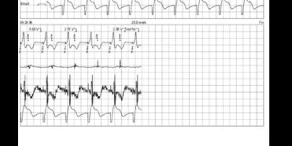
LV pacing threshold test performed in LV bipolar configuration (LV tip – LV ring / anode);
- this tracing allows visualizing the left ventricular bipolar electrocardiographic pattern;
A second LV pacing threshold test is performed in LV tip – RV ring (anode) configuration;
- a different electrocardiographic pattern is obtained;
- from 3.25 volts, modification of the electrocardiographic pattern which becomes similar to that observed during LV bipolar configuration (RV anodal capture threshold);
- In this patient, the loss of LV capture occurs at an amplitude below 1 volt / 0.4 ms (not shown on this tracing) which corresponds to the threshold value of the LV.
Other articles that may be of interest to you

This patient presents an anodal RV capture when the selected pacing configuration is LV tip – RV ring at the programmed value. During biventricular pacing with anodal capture, the electrocardiographic pattern features little or no changes compared to the traditional biventricular pattern. A 12-lead electrocardiogram, rather than a single lead by the programmer, is usually necessary to make the diagnosis. In this patient, the electrocardiographic pattern was slightly different on the distal end of the QRS in leads V2, V3 and V4. On the other hand, an anodal capture can significantly modify the analysis of the tracings when performing the left ventricular threshold test. The change on the electrocardiogram was very clear where the QRS varied between the biventricular pattern (LV tip + RV ring) followed by a left ventricular pattern (tip LV) for amplitudes of less than 3.5 volts. The actual left ventricular pacing threshold was less than 1 volt/0.4 ms.
As in this example, the pattern of the QRS complex can vary during the performing of a left ventricular threshold. In VVI mode at 110 bpm, the risk of fusion with spontaneous activation is greatly reduced. Two hypotheses can then be considered: 1) an anodal capture as on this tracing; 2) the presence of 2 left ventricular leads connected through a Y-connector. Modifying the left ventricular pacing configurations generally allows making a differential diagnosis. The double pattern is found in the case of anodal pacing when the configuration includes the right ventricular coil (only one pattern for the LV tip - LV ring configuration). In contrast, the double pattern can be found in all available configurations when two left ventricular leads are implanted if they have different pacing thresholds (bi-LV pattern followed by single-LV pattern).
In the absence of a demonstrated hemodynamic superiority of an anodal capture configuration, in view of the very small modification of the electrocardiographic pattern and in order to minimize energy consumption, an output amplitude at 2.5 volts/0.4 ms (without anodal capture) was preferred in this patient.