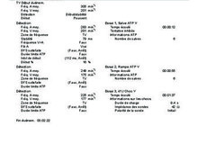
VF counter
Tracing
Manufacturer Medtronic
Device ICD
Field Counter
N° 2
Patient
Patient implanted with a single-chamber ICD (Protecta XT VR) for Brugada syndrome; hospitalization for syncope and electrical shock with VF tracing stored in the device memory allowing to focus on the functioning of the VF counter.

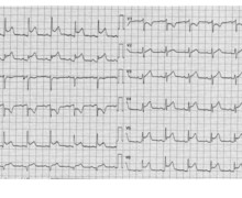
Graph and trace
The graph initially shows a regular slow rhythm followed by a sudden acceleration with ventricular intervals classified as VS then FS; detection of a VF episode, charge of the capacitors followed by shock delivery (35 Joules) enabling termination of the arrhythmia.
- the EGM shows an acceleration of the ventricular rhythm, the first intervals being initially classified as VS;
- the acceleration continues with certain intervals classified as FS;
- alternation between VS and FS intervals in spite of the absence of obvious undersensing, certain intervals being slower than the programmed VF zone;
- initial detection of a VF episode (counter programmed at 24/32);
- charging of capacitors with intervals systematically classified as VS;
- delivery of a successful electrical shock of 35 Joules;
- end of the episode after 8 consecutive intervals classified as VS.
Other articles that may be of interest to you


This tracing also allows underlining the characteristics of the probabilistic counter used in the VF zone. On the previous tracing, there was an intermittent undersensing during a VF episode with no significant impact on the detection of the episode, the probabilistic counter tolerating a maximum ratio of 25% of long intervals in conjunction with the undersensing. Conversely, on this tracing, the detection appears optimal with 100% of the ventricular signals in tachycardia correctly detected by the device. At the beginning of the tachycardia, however, some intervals are classified as VS being slower than the lower limit of the programmed VF zone (280 ms). The detection quality of a ventricular arrhythmia is multiparametric and is dependent on: 1) filters and amplification which are not programmable for MedtronicTM ICDs; 2) the amplitude of the ventricular signals with a limit set by the programmed sensitivity (nominal value 0.3 mV); 3) the variability in signal amplitude: the various characteristics of the adaptation of the sensitivity level during the cardiac cycle (percentage of adaptation, adaptation delay, slope of increase in sensitivity during the cycle) are not programmable; 4) the detection vector: MedtronicTM devices are the only devices that allow selecting (when the lead is not an integrated bipolar lead) between standard bipolar sensing (between the 2 distal electrodes) and integrated bipolar detection (between the ventricular coil and the distal electrode); in some patients, there may be a significant difference between the amplitude of the ventricular signals detected in one configuration or the other, hence justifying the prospect of systematically testing the other option in the presence of an under- or oversensing; 5) the number of intervals required to fill the counter, which is programmable; as seen previously, the percentage of fast intervals (X/Y ratio) is conversely not modifiable (still remains a ratio of 75%); 6) the limit of the programmed zones: in the new international guidelines for MedtronicTM devices, the limit of the VF zone is relatively low (between 187 and 200 beats per minute); on this tracing, this type of programming (limit at 300 or 320 ms) would have allowed obtaining a perfect classification at the beginning of the tracing; the programming of higher VF zones (> 220 beats per minute) increases the risk of delay or absence of detection of ventricular arrhythmias; 7) the type of counter used: one of the specificities of the devices of this manufacturer is that the counting method differs completely between the VT zone (consecutive intervals) and the VF zone (probabilistic counter).