Induction of ventricular fibrillation at the end of the implantation procedure
In this article
- Introduction
- Induction of fibrillation
- Delivery of the electrical shock
- Evaluation of sensing
- Verification of defibrillation efficacy
- The defibrillation threshold in practice
- Upper limit of vulnerability
- Upper limit of vulnerability in practice
- Advantages and limits
- Factors that influence the defibrillation threshold
- Management of patients whose defibrillation threshold is high at the time of device implant
- Risks and contraindications to the performance of the defibrillation test
- Must the defibrillation threshold be tested ?
The implantation of a cardiac defibrillator (ICD) usually ends with the induction of ventricular fibrillation (VF) to verify that the device properly detects and terminates the arrhythmia. Despite some risk involved, this test used to be performed systematically with older devices, which were implanted for secondary prevention indications, in patients at high risk of recurrent sudden cardiac death. Shocks were the only therapy available and defibrillation failures were relatively frequent. With contemporary devices, defibrillation failures are rare, most patients undergo device implantation for primary prevention indications, and anti-tachycardia pacing terminates a large proportion of rapid ventricular tachycardias. Furthermore, newer ICDs deliver shocks of considerably higher maximum energy, guaranteeing a wider safety margin. Consequently, whether to induce VF at the end of an implantation procedure is a decision made on a case-by-case basis.
The induction of VF allows to test the proper function of the implanted system and to :
- Verify the integrity of the high voltage system;
- Verify the proper sensing and re-sensing of the intracardiac electrograms during VF;
- Verify that the defibrillation safety margin is wide enough.
Three different modes are available to induce VF: DC FibberTM, shock on T and Burst.
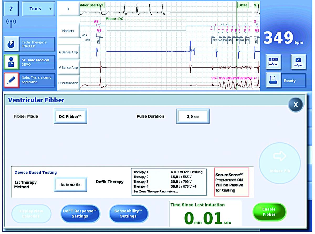
DC FibberTM :
DC FibberTM delivers a single 8 Volt direct current pulse through the high-voltage electrodes in order to induce VF.
Pulse duration: nominal 2 seconds (0.5…5 seconds)
Shock on T :
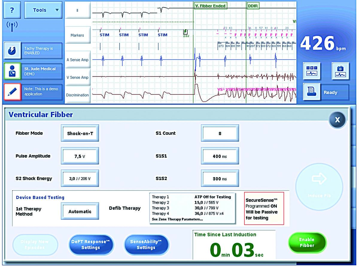
A shock is delivered on the T wave, i.e. in the vulnerable period; the right ventricle is paced at a fixed rate until a 1 - 2 J shock is delivered on the peak of the T wave, at a coupling interval of approximately 300 ms. The number of pulses is programmable between 2 and 25, the cycle length between 100 and 800 ms, the pacing amplitude at 5 or 7.5 V, the coupling of the electrical shock between 20 and 600 ms, and the energy delivered between 0.1 and 36 J;
Burst :
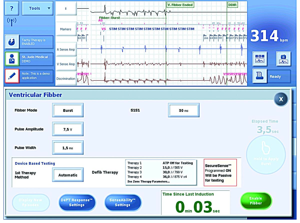
This fibber mode delivers bursts of stimuli at short cycle lengths with no extra stimuli. Bursts can be delivered for an extended time by holding the Hold to Apply Burst button.
Pulse amplitude: nominal 7,5 Volts (or 5 V)
Pulse width: nominal 1,5 ms (or 1,0 ms)
S1S1: nominal 30 ms (20 … 10 … 100 ms)
The success rate, i.e. the ratio VF induction / attempt, seems higher (>90%) with the delivery of continuous or alternating current than with the delivery of shocks on the T wave (approximately 80%). Furthermore, the arrhythmias triggered with continuous current seem more polymorphous than when triggered by T wave shocks. If the procedure is performed under local anesthesia, the painless alternating current is preferred to the other induction methods.
During the induction procedure, the electrical shock can be delivered by 3 different methods :
- Automatic; the device delivers the therapy after confirmation of the episode in the VF zone;
- Delayed; the device delivers the therapy after confirmation of the episode in the VF zone and after a programmable delay;
- Manual; the device charges the capacitors and the operator chooses when to deliver the therapy. If the procedure is performed under local anesthesia, VF is triggered by alternating current, and the shock is delivered manually after the patient has lost consciousness.
One of the main goals of the test is to verify the proper detection of induced VF.
- A low (~ 1 mV) sensitivity is usually programmed for the test. Proper sensing despite a low sensitivity indicates a satisfactory safety margin compared with the programmed value (0.3 - 0.5 mV);
- The sensing of a >5 mV R wave during sinus rhythm usually guarantees an early and proper detection of a VF episode. State-of-the-art ICDs rarely fail to detect VF if sensing during sinus rhythm is satisfactory. The test probably needs to be performed to verify the quality of sensing during VF only when sensing is poor (<3 mV) during sinus rhythm. However, the correlation between the R wave amplitude during sinus rhythm and the amplitude of the ventricular electrograms during VF is not perfect.
The other important objective of inducing VF during the implant procedure is to test the defibrillation efficacy. To allow the restoration of sinus rhythm, the electrical shock must change the ventricular myocardial transmembrane potential in order to eliminate the on-going fibrillatory waves without re-inducing the arrhythmia.
The defibrillation threshold (DFT) corresponds to the lowest energy that effectively defibrillates. In contrast with pacing, the DFT is not an absolute value, above which defibrillation is invariably successful and below which it is systematically unsuccessful. A given shock strength is associated with only a probability of success, such that the efficacy of a defibrillation shock is better represented as a curve of exponential probability, which is relatively reproducible among patients.
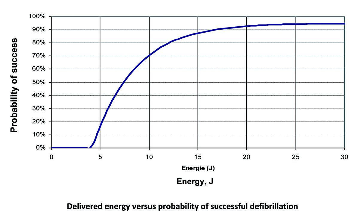
The aim of the test during the implantation procedure is to guarantee that, in a given patient, a shock of maximum strength delivered by the ICD has the highest probability of terminate VF.
Various methods can be used during the implant procedure to test the performance of the device :
- Actual measurement of the DFT by gradually decreasing the shock strength. This type of testing is no longer used clinically because of the excessively high number of shocks it requires;
- Test of a single shock strength allowing a sufficient safety margin compared with the maximum energy. The first shock is delivered at 10 J below the maximum capacity of the device. The efficacy of a shock can be verified by repetitive testing of the same amplitude, leaving 2 to 3 minutes in-between the defibrillation episodes to allow hemodynamic recovery and minimize the cumulative effect of the shocks. If the shock delivered by the ICD is ineffective, ≥1 rescue shock(s) can be delivered by an external device or by the implanted system, at the highest programmable energy. The use of an internal shock has the advantage of preventing a skin burn caused by the external defibrillator, though has the disadvantage of being delayed by the re-detection of VF and by the new charge time needed to reach the maximum energy.
Depending on the amplitude of the shock delivered and of its timing in the cardiac cycle, the effect can be opposite: a strong shock (30 Joules) delivered during a neutral period (synchronized to the R-wave) is likely to terminate an arrhythmia, whereas a low-amplitude shock (1 Joule) delivered during the ventricular vulnerable period (peak of the T wave) is likely to trigger an arrhythmia. There is a direct and strong relationship between these opposite shock effects. This hypothesis has been validated in different animal and human studies. A value directly linked to the “defibrillation threshold” exists above which a shock does not induce an arrhythmia. Consequently, an alternate defibrillation test consists of measuring the upper limit of vulnerability, which is the lowest energy delivered during the ventricular vulnerable period that does not trigger VF.
Determination of the shocking coupling interval: during pacing at high rate (400 to 500 ms pacing cycle lengths), measurement of the interval between the pacing spike and the peak of the T wave in multiple leads ECG.
Determination of the upper limit of vulnerability: deliver 3 to 4 shocks with different coupling (varying in 20 ms steps around the peak of the T wave) at high energy and if VF is not induced, progressively step down the energy until VF is induced; the last value that does not induce VF, defines the upper limit of vulnerability. This probabilistic value is closely correlated with the defibrillation threshold. For example, if a 20-J shock delivered during the vulnerable period does not induce an arrhythmia, the probability is high that a shock of same amplitude will terminate a ventricular arrhythmia. Determination of a safety margin: deliver 3 to 4 shocks with different coupling at a given energy (usually between 15 and 20 Joules) and if VF is not induced, this shock strength is superior to the upper limit of vulnerability suggesting an adequate safety margin.
As explained before, the major advantage is the possibility to confirm a safety margin without inducing VF and circulatory arrest, limiting the risks associated with the conventional procedures of defibrillation threshold testing (intractable VF, cerebral and myocardial ischemia, electromechanical dissociation). The reproducibility of the upper limit of vulnerability (same field delivered during the same pattern of repolarization) is also probably higher than the defibrillation threshold (same field delivered during changing and variable patterns of repolarization).
However, the upper limit of vulnerability is an indirect measure and does not provide information with regard to the ability of the device to detect VF. This test should therefore only be performed when sensing during sinus rhythm is correct (> 5 mV) predicting a high probability of reliable sensing during VF. Moreover, the peak of the vulnerable zone is narrow and delivery of a single T-wave shock without changing the coupling interval may lead to the underestimation of the upper limit of vulnerability if the shock is not delivered during the most vulnerable period. Optimally, three to four shocks should be performed changing the coupling intervals (varying in 20 ms steps relative to the peak of the T wave). Therefore, vulnerability testing may reduce the risks related to VF but does not reduce or even increases the risks associated with the shocks (a minimum of 3 to 4 shocks being required).
Several patient-related factors, the implanted instrumentation, the ambient drug therapy or the occurrence of complications may have direct effects on the DFT.
The following patient characteristics have been associated with elevated DFT:
- Male gender;
- Large body surface;
- Low left ventricular ejection fraction;
- Left ventricular dilatation or hypertrophy;
- Presence of hypertrophic cardiomyopathy or Brugada syndrome.
The following shock characteristics influence the DFT:
- The shock waveform and duration of the phases of a biphasic shock; in the case of a fixed tilt, the shock is interrupted when the residual voltage of the capacitors has reached a predetermined percentage. The duration depends on the impedance while the delivered energy is fixed. The tilt of both phases is identical. In the case of a biphasic shock, the first phase plays the role of a monophasic shock, though with a lesser critical mass, while the second phase brings the membrane potential as near to zero as possible in order to prevent the re-induction of VF. The optimal duration of the second phase depends on the duration of the first, on the defibrillation impedance and on a membrane time constant. When the defibrillation impedance is high and the tilt fixed, the length of phase 2 is excessive. If the defibrillation impedance increases, the first phase must lengthen while the second must shorten, which is not what happens if the tilt is fixed. For a defibrillation impedance within a normal range, a 65% fixed tilt remains near the optimal duration of the first phase. Practically, when, during a performance test, the defibrillation impedance is high (>60 Ohms for a simple coil or >75 Ohms for a double coil), it seems preferable to immediately optimize the duration of both phases;
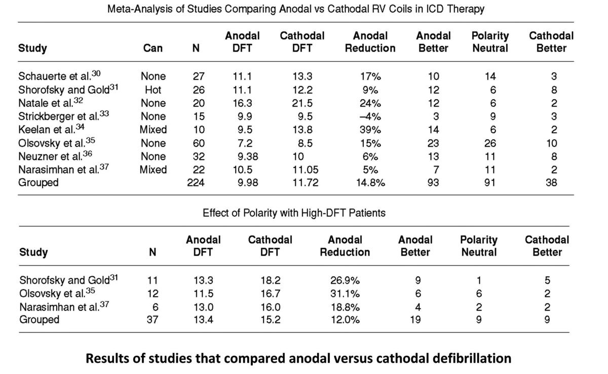
- The shock polarity; the DFT is lower with a right ventricular electrode used as an anode for the first phase of a biphasic shock, particularly when the DFT is high (the anodal threshold is the same or lower than a cathodal threshold in 76% of patients whose threshold is high). The nominal polarity of Abbott ICD is anodal.
The orientation of the shock vector must cover the left ventricle uniformly; this vector depends on the position of the defibrillation coil(s) and of the pulse generator with respect to the heart. The distal right ventricular coil must be entirely contained inside the ventricular cavity, while the proximal coil of a dual-coil electrode must be placed high enough to prevent the dissipation of current at the level of the right atrial cavity. Placing the proximal coil inside the superior vena cava may be challenging. If it is floating inside the right atrium, it might be preferable to use the lead as a single coil.
The greater defibrillation efficacy contributed by a dual coil lead is currently debated and seems less important since the tilt and duration of each phase of shocks delivered by single coil leads can now be optimized. Furthermore, since current ICDs deliver maximum shock strengths that are higher than previous generations of devices, this additional gain of energy has a greater impact on the shock efficacy than the use of a dual coil lead. Finally, when a dual coil lead needs to be extracted, forexample because of an infection, the presence of a proximal coil promotes the adhesion of the lead to the wall of the superior vena cava, complicating and increasing the procedural risk.
The following medications influence the DFT:
- Amiodarone increases significantly the DFT, particularly when it is already high;
- Class IC antiarrhythmic drugs and verapamil also increase the DFT;
- Sotalol, dofetilide and azimilide lower the DFT and can be used preferentially in patients in whom it is high.
Procedural complications that influence the DFT:
- The presence of a pericardial or pleural effusion, or of a pneumothorax can increase the DFT;
- By creating a parallel circuit, the persistence of an old lead’s fragment might shunt a part of the delivered energy.
Various options are available for a patient whose DFT is high:
- Lower the likelihood of a high threshold by placing the entire distal coil inside the right ventricle and implant a high shock energy ICD;
- Verify the quality of the connections between leads and pulse generator before starting the test;
- Eliminate reversible causes, such as ischemia, metabolic disorders, and complications, such as effusions or pneumothorax;
- Change the shock characteristics, including waveform, polarity and, with dual coil leads, the shock vector;
- Verify the non-dislodged and satisfactory position of the intraventricular, high-voltage electrode, which must be entirely inside the ventricle. If it is in a proper position, try positioning the lead higher if it is at the apex, or toward the apex if it is on the septum;
- If the threshold remains high, instead of replacing a single by a dual coil lead, consider implanting an electrode under the skin or a lead in the coronary sinus.
The risks associated with the defibrillation test include complications attributable to the shock as well as to the induction of VF, namely:
- The temporary cardiac arrest causes cerebral ischemia, especially after several unsuccessful shocks and a long duration of VF;
- In presence of coronary artery disease, VF can cause myocardial ischemia with electrocardiographic changes and increases in blood troponin concentrations. The shock itself can increase the blood concentration of troponin, though the rise seems greater in patients presenting with coronary disease;
- The mortality due to VF refractory to internal and external shocks is not >0.1%, though it is not zero;
- In the presence of intracardiac thrombus, a systemic embolism may complicate the delivery of a shock. This risk is particularly real in patients presenting with atrial fibrillation, as anticoagulation is usually interrupted or decreased before and after the ICD implantation procedure, increasing the risk of thrombus formation. Left ventricular thrombi are also common in patients suffering from heart failure. The systematic performance of transesophageal echocardiography might be considered before implanting an ICD in patients presenting with atrial fibrillation.
Using state-of-the-art devices, implantation on the left side is associated with a 90% success rate of shocks with 10-J margins, while shocks of maximum strength are associated with success rates approaching 95%. The need to change the lead position or the defibrillation system altogether does not seem to be >5%.
- Therefore, to eliminate the risk of undersensing, this test is indispensable when the ventricular electrograms during sinus rhythm are <5 mV. The test should also be performed in patients at risk of a high DFT and who present with risk factors, such as young age, obesity, coronary artery disease, heart failure, Brugada syndrome, amiodarone therapy and others;
- Conversely the test is contraindicated in presence of intracardiac thrombus, insufficiently anticoagulated atrial fibrillation, severe aortic stenosis, unstable coronary artery disease or decompensated heart failure;
- In all other patients, whether to test or not test a device that has been implanted depends on the medical center’s customs, the implantation indication, where secondary prevention leans in favor of the test and primary prevention is more debatable, and on the patient’s age and clinical characteristics;
- Whether to test a pulse generator that has been replaced should take in consideration that the safety margin might have changed from the time of original device implantation. The DFT might, therefore, be tested if it was not done in the first place, if heart failure has worsened, or if a treatment known to increase the threshold has been introduced.


