
Chapter 2 · Therapies · Case 2
Lead dysfunction and DynamicTx™ algorithm
Patient and episode
Patient
- Man implanted with a triple-chamber defibrillator 12 years ago; device replacement 3 years ago; syncope with electric shock
Summary
- Episode of VF recorded in February 2021, treated with a sequence of PACE, a 30-joules electric shock that was not delivered, and a 36-joules electric shock. Alert: possible lead malfunction with high-voltage lead impedance out of range The initial shock configuration is programmed to RV to VCS/device: the impedance of this first shock is < 10 Ohms; the configuration of the second shock was automatically changed to RV to device with an impedance of 76 Ohms
The recording
Tap a number on the trace, or an entry in the list below
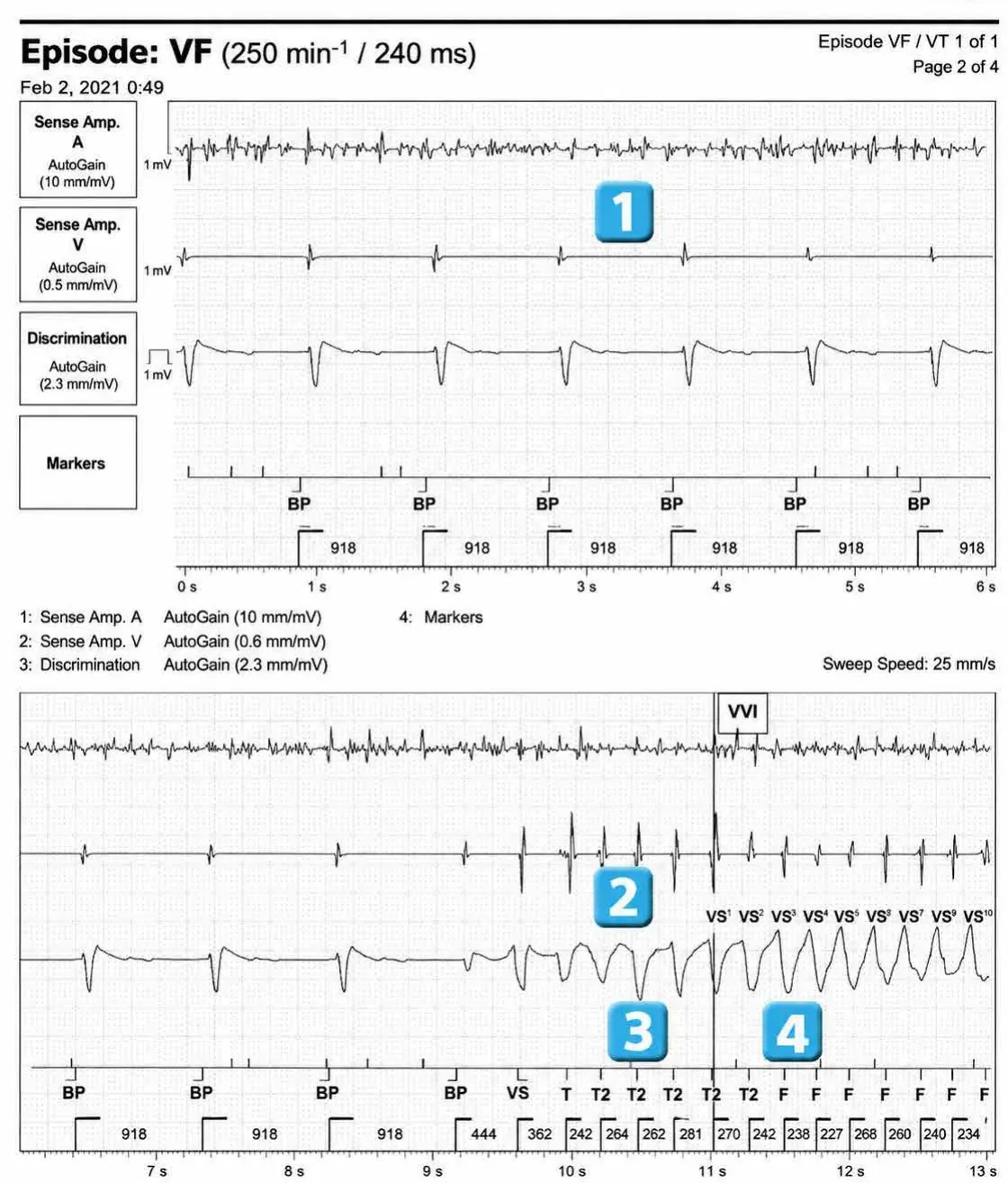
- FA + biventricular pacing
- onset of polymorphic ventricular arrhythmia; the first two cycles are classified as transitional (discrepancy between the current interval and the average of the previous four cycles)
- first cycle classified as T2 (concordance between the current cycle and the averaged cycle)
- after 4 cycles classified as T2, first cycle classified as F
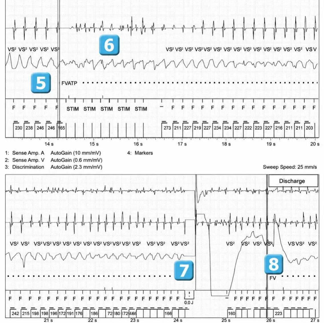
- after 12 cycles classified as F, detection of an episode of VF (VF counter completed)
- burst during charging (start of capacitor charging)
- At the end of charging, the 30 joules electric shock (HV: High Voltage) is unsuccessful and canceled (0 joules).
- Redetection after 6 cycles classified as F
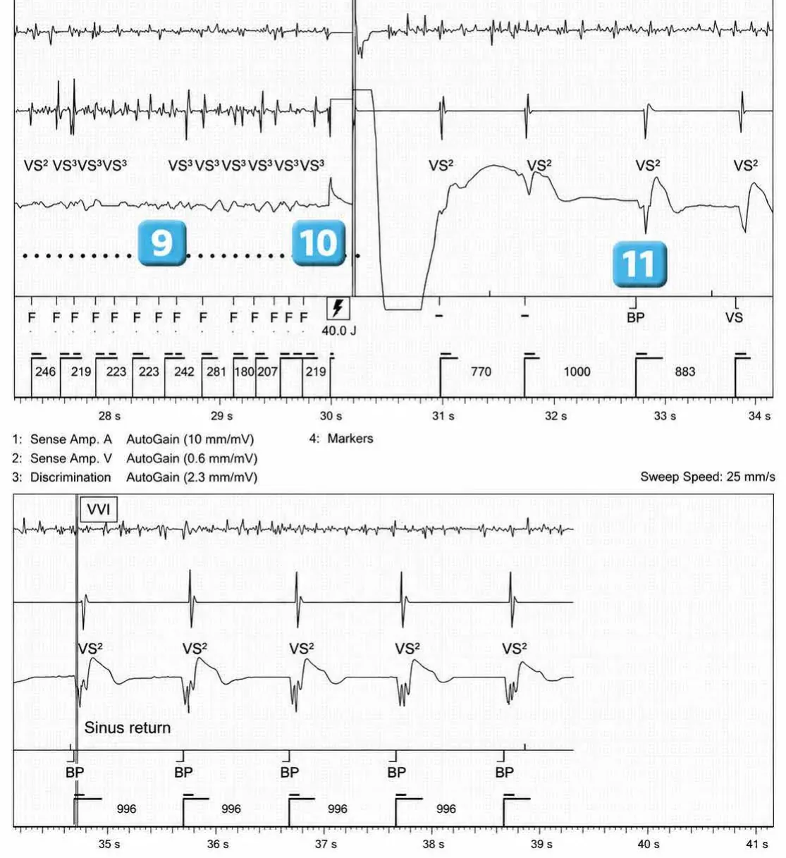
- Charging of capacitors
- 40 joules shock
- arrhythmia reduction
Points to remember
- This trace illustrates the value of the DynamicTx™ algorithm in reducing a VF episode in a patient with lead dysfunction. This patient had a Riata dual-coil lead implanted. During this episode of VF, the superior vena cava coil and the lead housing served as the cathode for the first phase during the first shock (nominal configuration: RV to SVC/lead housing). The first shock was not delivered because the device detected high voltage impedance < 10 Ohms (short circuit on the high voltage defibrillation circuit). A second configuration was then automatically selected (RD to lead). The second shock (normal impedance) reduced the arrhythmia and restored a viable rhythm.
- A short circuit in the defibrillator’s high-voltage circuit can have catastrophic consequences in the event of VF, with the risk that the shock will not be delivered effectively; this problem can be observed with various types of leads on the market. A number of Riata leads have had a problem with insulation, sometimes located under the defibrillation coils, which may be associated with a risk of short circuit. Signs of short circuit were often undetectable during device interrogation or telemedicine monitoring and only became apparent following an electric shock on a spontaneous or induced arrhythmia.
- The DynamicTx™ algorithm was developed with the goal of delivering an effective electric shock even when a short circuit is detected by the device during an arrhythmia episode.
- The DynamicTx™ algorithm is programmed as standard on all recent platforms and is compatible with all dual-coil defibrillation lead models; it is only active if the superior vena cava coil is activated.
- Before delivering a shock, the device checks the integrity of the shock vector. If integrity is compromised (current too high > 60 amps), the shock is not delivered to avoid potential destruction of the defibrillation circuit (if the malfunction is located in the box); the HT shock vector is then modified; as in this example, if the initial configuration (VD to VCS/box) shows signs of malfunction, an alternative configuration (VD to box) is tested (possible problem with the VCS coil); if this second configuration also shows signs of malfunction, a third configuration (VD to VCS) is then tested (possible problem with the box).
- The shock vector can be adjusted in the DeFT Response™ settings; it is important to remember to program the defibrillation shock (single coil versus dual coil); if this is not done, the dual coil configuration will be used by default; if a non-Abbott single coil lead is used and the model name is entered in the device data, the configuration (single versus dual coil) will be automatically adjusted; in the case of a non-Abbott single coil lead that is not programmed as such, an impedance error will occur
Practice out loud
Just describe the tracing. What do you think is going on? Describing the numbers can help.
00:00
0%
—
From Implantable Cardioverter Defibrillator — clinical cases based on tracings by P. Bordachar, M. Strik, A. Thiyagarajah, S. Ploux. Published by Cardiocases. Every numbered marker on a recording is explained in the list beneath it; tap a marker on the trace or an entry in the list.