Basic concepts
The induction of VF at the end of the procedure allows to test the proper function of the implanted system and to:
- verify the integrity of the high voltage system
- verify the proper sensing and re-sensing of the intracardiac electrograms during ventricular fibrillation
- verify that the defibrillation safety margin is wide enough
Despite some risk involved, this test used to be performed systematically with older devices, which were implanted for secondary prevention indications, in patients at high risk of recurrent sudden cardiac death. Shocks were the only therapy available and defibrillation failures were relatively frequent. Failure to defibrillate, nowadays, is rare, a majority of patients undergo device implants for primary prevention, and a large proportion of rapid VT can be terminated by ATP. Furthermore, the maximum strength of the shocks delivered by the latest implantable defibrillators is higher and associated with a wider safety margin.
This has prompted many implanting centres to reconsider the need for a systematic test at the end of the procedure and, instead, to proceed on a case-by-case basis.
Induction of ventricular fibrillation
Several means of VF induction are available in clinical practice:
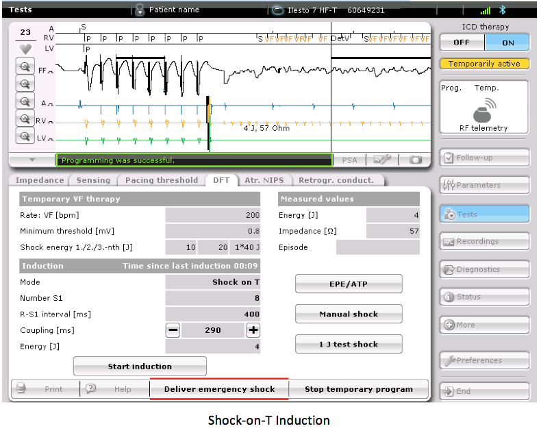
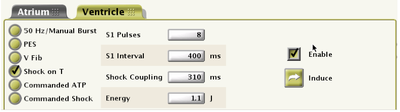
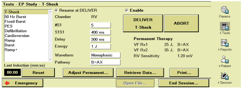
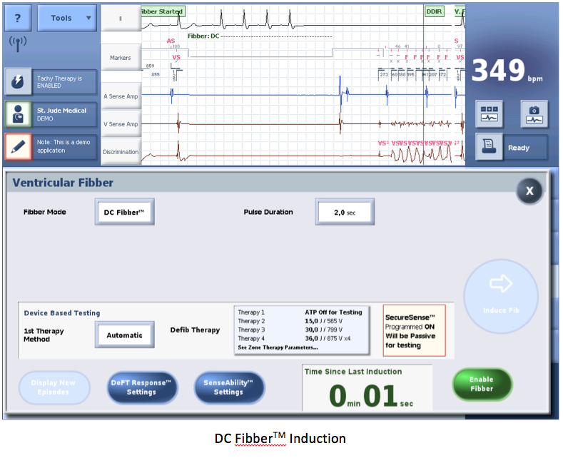
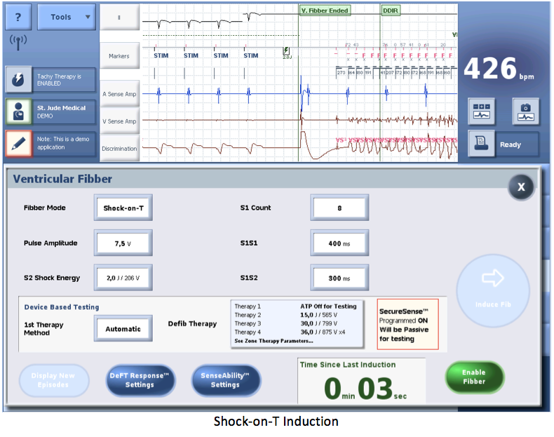
- T wave shock delivery: a low energy shock is delivered during the ventricular vulnerable period to induce a ventricular arrhythmia (most often VF). A ventricular stimulation sequence, at a fixed rate is followed by the delivery across the electrodes, of a low-energy electrical shock during the ventricular vulnerable period. The delivery of the shock requires the prior charge of the capacitors.
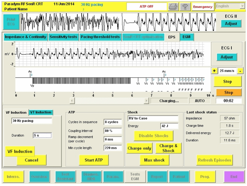
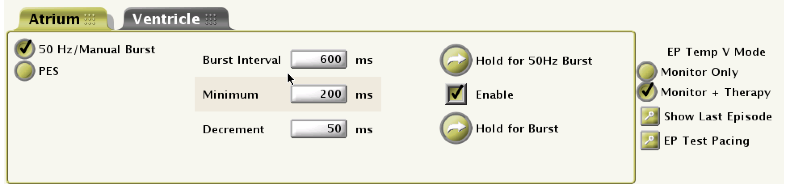
- Delivery of alternating current: a salvo of rapid pacing (alternating current) is delivered to induce an arrhythmia (VT or VF). Several rates are available according to the manufacturers: 33 HZ à 30 ms between pulses; 50 HZ à 20 ms; 20 HZ à 50 ms.
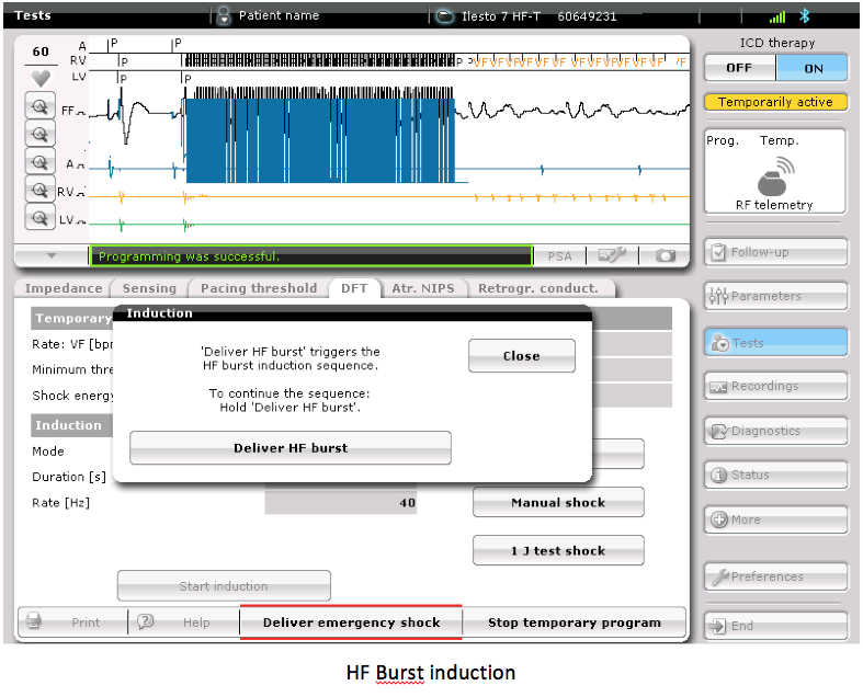
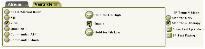
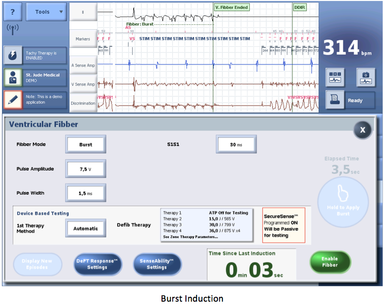
- Delivery of high rate, high output pulses: pulses are delivered through the shocking electrode with 2 different cycle lengths to induce a ventricular arrhythmia (most often VF).
- The success rate, i.e. the ratio VF induction / attempt, seems higher with the delivery of direct or alternating current (may minimize the number of needed attempts) than with the delivery of shocks on the T wave. Furthermore, the simplicity of programming is higher with continuous or alternating current since only one programmable parameter is needed. If the procedure is performed under local anaesthesia, the painless alternating current is preferred to the other induction methods.
Delivery of the electrical shock
During the induction procedure, the electrical shock can be delivered by 3 different methods:
- Automatic: the device delivers the therapy after confirmation of the episode in the VF zone.
- Delayed: the device delivers the therapy after confirmation of the episode in the VF zone and after a programmable delay.
- Manual: the device charges the capacitors and the operator chooses when to deliver the therapy. If the procedure is performed under local anaesthesia, VF is triggered by alternating current and the shock is delivered manually after the patient has lost consciousness.
Defibrillation testing in clinical practice
A number of different protocols can be used. Many of these do not aim to measure the actual defibrillation threshold; rather they set out to determine that a device is likely to provide an adequate safety margin. Indeed, determination of a complete curve probability of success/energy delivered would require many more episodes of fibrillation/defibrillation than practically and safely acceptable. In clinical practice, different protocols can be performed:
- Step-down to failure testing: the first shock energy is usually programmed at 10 Joules less than the maximum output of the device. Progressively lower energies are then used at successive inductions (for example steps of 5J lower energies for each successive test) until there is failure of defibrillation. The defibrillation threshold is taken as the lowest successful energy. This type of testing is infrequently used clinically because of the excessively high number of shocks it requires. Moreover, the word threshold is not adequate for defibrillation because of the probabilistic nature of defibrillation. This method may lead to programming the first shock to a value less than the maximal output.
- Test of a single shock strength twice: a first shock is usually delivered at 10 J below the maximum capacity of the device. To verify the effectiveness of the shock, the same amplitude is then tested a second time. If the 2 shocks reduce the arrhythmia, it suggests an appropriate safety margin. This method may lead to programming of the first shock at the maximal capacity of the device.
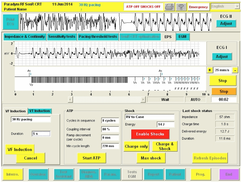
- Test of a single shock strength once: a single shock (for example 14 Joules: at least 15 Joules below the maximum output of the device) is tested. Similarly, if this shock is successful, it suggests an appropriate safety margin.
At least 3 -5 minutes are allowed between every VF induction to permit hemodynamic recovery and to minimize the cumulative effect of shocks.
If the shock delivered by the implantable defibrillator is ineffective, ≥1 rescue shock(s) can be delivered by an external device or by the implanted system, at the highest programmable energy. The internal shock does not carry the risk of thermal injury to the skin, though has the disadvantage of being delayed by the re-detection of VF (unless using the commanded shock mode) and by the new charge time needed to reach the maximum energy.
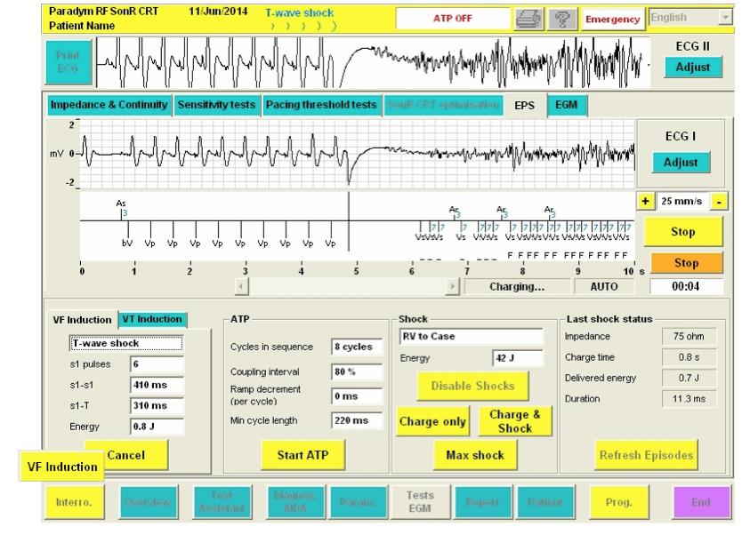
 VF Induction: Instructs the defibrillator to deliver the burst. Once pressed, this button changes to Cancel.
 Cancel (VF): Stops VF induction if it is not complete and restarts the defibrillator automatic arrhythmia detection and therapy. Once the induction is completed, automatic arrhythmia detection restarts and therapies are applied as programmed.