Spontaneous T-wave oversensing

Basic concepts

T-wave oversensing remains a significant problem in modern ICD systems and has been reported to occur in up to 8% of patients. It may cause inappropriate shock delivery during normal sinus rhythm particularly during exercise when both RT and TR intervals fulfill the VF detection rate. T-wave oversensing is usually divided into oversensing of the paced T-waves, oversensing of spontaneous T-waves in presence of an adequate R-wave and oversensing of spontaneous T-waves in presence of a small R-wave.

The requirements of the sensing circuitry of an ICD are different than those of a pacemaker since the need to detect rapid rhythms precludes the programming of long and fixed ventricular blanking periods, the need to detect fast, polymorphic, low-amplitude signals precludes programming low and fixed sensitivity, with the concomitant need to ignore T-waves.

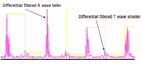
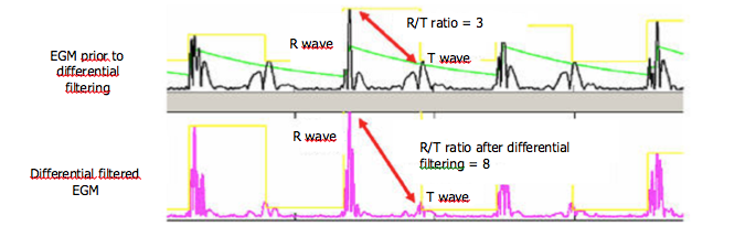
The crucial step to minimize T-wave oversensing is the choice of the range of bandpass filters by the manufacturers (difference between the high and low pass filters). The slew-rate of the T-wave (smooth signals) is less than that of the R-wave (sharp signals), with a usual frequency less than 5 Hz, but may change with use of drugs, ischemia, sympathetic tone or metabolic abnormalities. In some situations, the filters and the sensing amplifiers may not provide a large enough absolute difference between the R-wave amplitude and the T-wave amplitude. The amplitude of the T-wave may exceed the auto-adjusting threshold leading to T-wave oversensing.

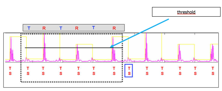
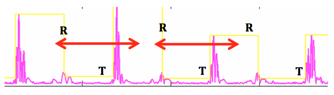
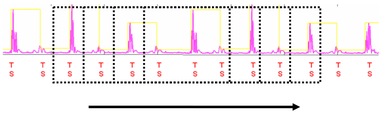
T-wave oversensing is associated with a typical aspect of alternating high-frequency (R-wave) and low-frequency (T-wave) signals on the near-field electrogram. The device counts the T-wave as an additional ventricular event doubling the measured ventricular rate. The magnitude of the alternation in intervals may also be important at low heart rate with a short QT interval (short RT and longer TR interval) but may be smaller especially during tachycardia and/or if the QT is prolonged (RT and TR nearly equivalent). 

Three electrical patterns can lead to oversensing of the T wave after spontaneous beats:

  1. Delayed T-wave: it is likely to be observed in patients with long QT syndrome in whom repolarization is delayed when the ventricular sensitivity is at maximal level. Moreover, in these channelopathies, the QT interval, the morphology and amplitude of the T-wave can be modified dynamically increasing the risks of inappropriate therapies during exercise.
     
  2. High amplitude T-wave and adequate R-voltage: this can be observed in hypertrophic cardiomyopathy, short QT syndrome resulting in tall Q-wave, some forms of long QT syndrome, electrolyte abnormalities (hyperkalemia, hyperglycemia) and some uncommon but reversible causes of repolarization changes like alcohol intoxication.
     
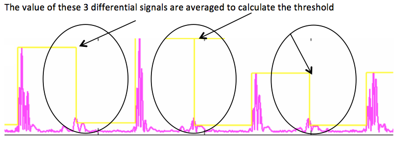
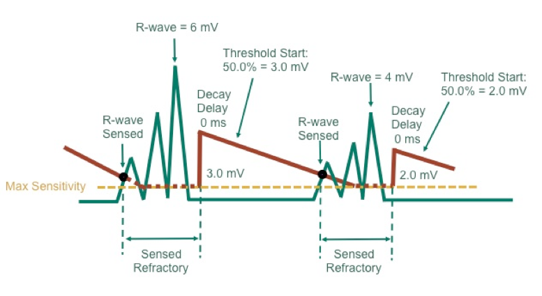
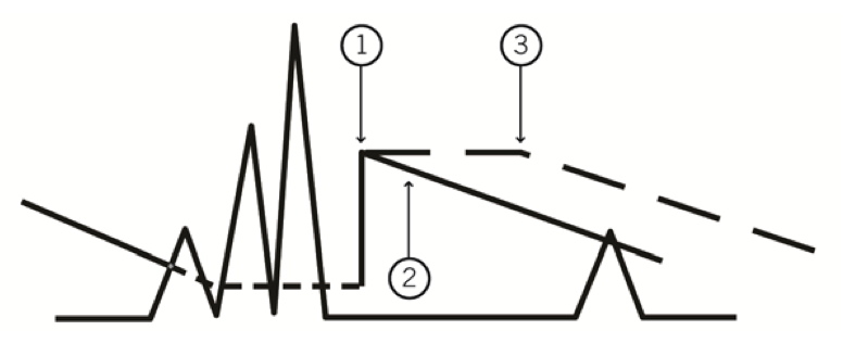
  3. Small R-wave:  when the R wave is of low voltage, oversensing of the T-wave becomes more likely to occur since the sensing threshold is automatically adapted to the R-wave amplitude and decreases over time. As a result, the device rapidly reaches high levels of sensitivity earlier in the cardiac cycle. Rapid deterioration of the amplitude of the R wave after implantation can be a manifestation of lead microdislodgement. Low R-wave amplitude can also be observed in patients with arrhythmogenic right ventricular cardiomyopathy, Brugada Syndrome, cardiac sarcoidosis, dilated cardiomyopathy involving the right ventricular chamber and can be a sign of disease progression.

In a limited proportion of cases, T-wave oversensing can be avoided by eliminating reversible causes. Large and/or delayed T waves can be corrected by reprogramming (variable possibilities according to different manufacturers) whereas the reprogramming options are limited in case of low-voltage R-wave and lead revision is often necessary.

To noninvasively manage T-waves oversensing, different options can be proposed: decreasing ventricular sensitivity to a less sensitive level (may be associated with undersensing of true VF particularly if the R-wave is small), lengthening the post-ventricular refractory period (most of the time ineffective), increasing the interval detection count or programming the tachycardia detection rate above twice the expected exercise-induced maximum heart rate (no impact on the occurrence of oversensing but decrease in the risk of inappropriate therapies). Administration of drugs like beta-blockers can be proposed to slow the heart rate.

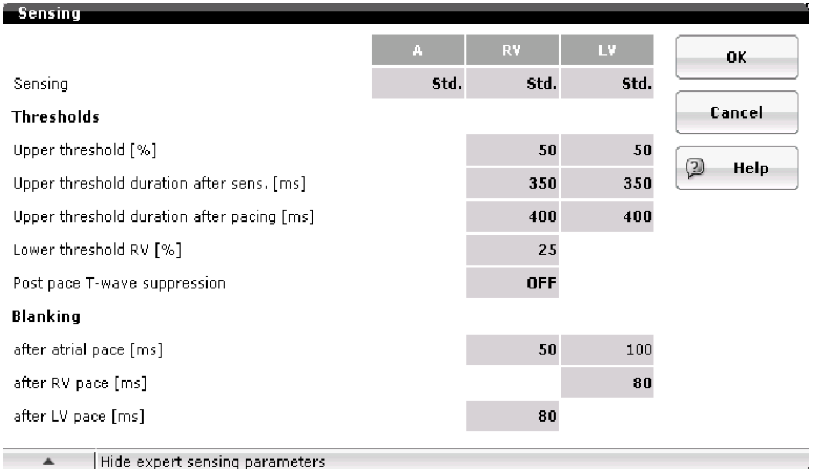
Some manufacturers (Biotronik and Abbott) provide other specific means to cover the T-wave signal: programmable threshold start, sensing decay delay and adjustable band pass filter for ventricular sensing.

The alternation of morphologies and/or intervals may be exploited to discriminate T-wave oversensing with a true VT using morphology and/or stability discriminators.

Medtronic has also developed a specific algorithm that withholds therapy when T wave oversensing is identified. The aim is not to prevent T-wave oversensing but to provide the appropriate diagnosis and to prevent the consequences.

Some of these programming features may compromise reliable sensing during VF. A revision of the system is required if the safety margin for sensing VF is insufficient (typically T-wave oversensing with low-voltage R-wave). Manufacturer-related differences in lead design and device-based signal processing and possible manufacturer specific lead/generator compatibility may explain why in clinical practice, the rate of T-wave oversensing seems to be different from one manufacturer to another without definitive testing from large, randomized studies. In some situations, a change of device manufacturer can be proposed with in some cases, resilution of the problem.

T-wave oversensing may be RV site-specific and if a new lead is implanted, the operator will try to relocate the electrode to a position with an R wave of greater amplitude and an increased R/T ratio. In infrequent situations, none of the RV sites provides acceptable signals (severe arrhythmogenic right ventricular cardiomyopathy) and surgical positioning of the high-voltage lead on the left ventricle has been performed. 

Specificities

The probability of T-wave oversensing and the possible reprogramming options are different according to the manufacturers.

Biotronik

In Biotronik defibrillators older than the Lumax 740, the bandwidth of the filters ranged between 24 and 60 Hz. Since the 740 models, the bandwidth has been widened to between 24 and 100 Hz.

A choice of 3 settings is available to control the sensing function and analysis of the right ventricular EGM:

  1. standard programming (Std)
     
  2. enhanced T wave suppression (TWS)
     
  3. enhanced VF sensitivity (VFS)

Enhanced T wave suppression

This programming, designed to prevent T wave oversensing modifies 2 settings: 1) the upper threshold is increased to 75% of the R wave amplitude (instead of 50% in the case of standard programming) for a 350-ms period, while the lower threshold is at 25%; 2) the filters are modified to prevent the amplification and sensing of the T wave: the high-pass filter is increased to 32 Hz (24 Hz in the case of standard programming). This programming is discouraged when the quality of sensing is low or medium.

Some additional settings can be programmed independently and individually to optimize the quality of ventricular sensing and decrease the rate of inappropriate T-wave oversensing. However, the access to these settings is protected by a code known only by the employees of Biotronik Inc.

icd_in_20_cs_t_wave_over1.png

Boston Scientific

The rate of T-wave oversensing has been traditionally very low with Guidant or Boston Scientific devices. This may be related to the shape of the first, second and third order filters more than the bandwith of the filters, which is standard for the high-pass (between 20 and 85 Hz).

The possibilities of reprogramming are limited in case of an infrequently described T-wave oversensing (no possibility of reprogramming the upper threshold, the decay delay, the filters...).


Medtronic

In the recent devices, bandwidth of the filters is between 20 and 39 Hz.

In case of T-wave oversensing, the possibilities of reprogramming are limited (no possibility of reprogramming the upper threshold, the decay delay, the filters...).

However, the way of counting the cycles (consecutive cycles required in the VT zone) provides good discrimination when the heart rate is not too high (cycle length in the VT zone) and T-wave oversensing is intermittent (some cycles without T-wave oversensing labeled VS resetting the counter to 0). Moreover, the change from true bipolar to integrated bipolar sensing, permitted in new Medtronic devices, can sometimes lead to an increase of the R-wave amplitude and an increase in the ratio R/T wave amplitude that solve the problem.

T wave discrimination

This new algorithm has been developed to withhold therapies when the device recognizes T-wave oversensing without interfering with the detection of true ventricular arrhythmias (no change in the sensing circuitry). It is nominally ON in the most recent devices.

This algorithm is based on the recognition of the physical differences of the R and T waves and on the alternation of these 2 signals. The slew rate of the R wave is generally higher than that of the T wave, a difference that can be amplified by a high-pass differential filter, which examines differences in amplitude, slew rate, and pattern to distinguish R from T.

The analysis becomes active once a rapid ventricular rate has been identified (VT count = 2, VF count = 3). Only ventricular sensed events above the programmed VT or VF detection zones are analyzed. This algorithm applies at both initial detection and at redetection without limitation imposed by the SVT limit or the High-Rate Time out. In contrast, it does not operate in the VT monitor zone.

This algorithm distinguishes the R and T waves according to different steps:

1) Discrimination of R waves and T waves through differential filtering of the sensing signal 

icd_in_20_cs_t_wave_over2.png

2) Determining the R and T wave discrimination thresholds   

icd_in_20_cs_t_wave_over3.png

3) Re-Evaluation of R and T waves

icd_in_20_cs_t_wave_over4.png

4) Applying the discrimination criteria to R and T waves

a. The amplitude of the tentative R and T waves must be stable on filtered EGM

b. The R-T coupling interval must be stable.

c. The R/T ratio from the filtered EGM must be <R/T ratio from the differential EGM.

icd_in_20_cs_t_wave_over5.png

d. The R-T pairs must satisfy a pattern of alternating R and T waves.

e. The corrected R-R interval is calculated

icd_in_20_cs_t_wave_over6.png

If all criteria are satisfied in the set of 6 intervals, the latter is classified as TWOS and a counter is incremented by 1. If a single criterion is not met, the set is classified as normal (no TWOS). The next group of 6 events is then evaluated, using a rolling window.

As long as 4 of the last 20 cycles satisfy the T wave criteria, TWOS is confirmed.

icd_in_20_cs_t_wave_over7.png

Abbott

When a patient faces T-wave oversensing, different settings for the following parameters can be changed:

  • the sensed ventricular refractory period (125 or 157 ms); there was previously a restriction in the possibility to program only 1 fast VF zone when this refractory period was programed at 157 ms; this restriction has been suppressed in the new platforms.
     
  • the threshold start: upon expiration of the sensed refractory period, the sensing threshold automatically adjusts to a percentage of the maximum amplitude of the sensed signal with an absolute maximum value of 6 mV in the ventricle and minimal value of 1 mV. The post-sensed threshold start can be set at 50, 62.5, 75 or 100%. If the amplitude of the ventricular signal is > 6 mV, the threshold start is 6 mV if 100% or 3 mV if 50%. If the amplitude of the signal is < 1 mV, the threshold start is 1 mV.
     
  • the decay delay: this parameter determines the amount of time after the sensed refractory period that the threshold remains at the programmed setting before beginning its decay to the programmed sensitivity level. The decay delay is programmable at 0, 30, 60, 95, 125, 190 or 220 ms.
     
  • the maximum sensitivity
     
  • low frequency attenuation : the advanced settings button enables to turn the Low frequency attenuation filter On or Off.

icd_in_20_cs_t_wave_over8.png

This figure shows the sensing circuit with a threshold start programmed at 50% and a decay delay at 0 ms.

icd_in_20_cs_t_wave_over9_0.png

  1. Threshold Start
     
  2. Decay Delay of 0 ms
     
  3. Decay Delay of 60 ms

This figure shows the potential interest of prolonging the decay delay to avoid T-wave oversensing.

The nominal values depend of these different parameters depend on the programing of the low filters attenuation (LVA):

  • LVA on: ventricular sensitivity 0.5 mV, threshold start 50%, decay delay 0 ms
     
  • LVA off: ventricular sensitivity 0.3 mV, threshold start 62.5%, decay delay 60 ms

The new algorithm SecureSense (comparing the signals in the near versus far-field channels) initially designed to prevent inappropriate therapies related to lead dysfunction may be proved to also reduce the rate of inappropriate therapies for T-wave oversensing (T-wave oversensing in the near field but not in the far-field channel).  


Microport CRM-Sorin